Yes, but what is it?
Fri 14 February 2025 by JuliaI wanted to make something tangible, useful, and a where I can use both metal working, and wood working. The idea for this project came into my head relatively fully formed a few weeks ago. I ordered the materials, and got to work.
Machining is about 90% work holding. If you can sort your work holding out, you’re a long way towards being able to make what you want to make.
And so I started at the lathe, by putting an M8 thread on the end of a length of 8mm 1.2510 (O1 to those of a Leftpondian persuasion). Using a tail stock die holder, and a new die set I bought myself.

This part complete, it goes in my tool bag, I don’t need it now, it’ll come in useful later.
So we start with the project proper. A disk of brass, 60mm in diameter and just over 6mm thick. Goes in the lathe so I can put a machined surface on one face, and conveniently get rid of most of the saw marks.

The part is very thin, and is held with the mearest of grip. But it’s enough that I can take some light passes. I don’t quite get all the saw marks off, I’m worried about making it too thin. But it’s enough for what I need at this stage. Part complete (for now), it goes into my tool bag.
Next up. A jig. Aluminium takes the stage now, with a square of 10mm thick aluminium plate. I covered the aluminium with blue layout fluid, found the centre, and punched it with a centre punch. Next up a game of musical chucks, as I swapped the 3 jaw chuck for a 4 jaw, and chucked up the aluminium.

To get the square aluminium plate kinda centred (esp as one side is not exactly well sawn) a dead centre, held against the centre punched dent by the live centre in the tailstock, allows the chuck jaws to be adjusted until the dead centre runs mostly true. I could have put a dial indicator on this, but for this part, as long as it’s mostly centred, it doens’t matter.
I forgot to photograph the next step, but it involved boring a through hole through the aluminium that was at least 18mm in diameter. I then used a boring bar to take a pass of this hole. Measuring the hole allowed me to set the dimensions into the Digital Read Out (DRO) on the lathe. This is crucial for the next part, as I can’t measure the feature I’m about to cut with any of the tools I own. I used the boring bar to then take a facing cut across the front of the aluminium, out to 60mm as marked on the DRO. The depth of this cut was about 400 microns. Not exacly deep. The key aim here is that the recess that I cut should be machined flat, and it should be a snug fit for the brass disc. I also put three grooves in the bottom of the recess to help adhesion. Some CA glue was then applied to the recess, and the brass disc put in place.

The jacobs chuck in the tail stock was used to apply pressure to the brass disc. It’s installed machined side down. Machined side to machined side. Held there with the CA glue. CA glue and sacrificial aluminium arbors/jigs is an excellent way of solving many work holding problems.

My slight screw up in all this was that the 80mm aluminium plate was too small to fit on the top part of the chuck jaws, so I had to put it down one layer, this meant I then had to do all machining here taking great care to avoid the spinning jaws of death. Switching the tool post round did the trick. I faced off the front of the disc, and then put a light chamfer on the corner. Afterall, chamfers are what seperate us from the animals…
I now have two faces of the brass machined such that they are coplaner, and the disc itself is held in a sacrificial aluminium arbor. I double check everything to make sure there’s nothing else left to do with this setup. The moment I release the chuck jaws I lose concentricity as well as the coplanarity of the workpiece. Happy I’m done for this stage, I take it out the chuck, and we move to the mill.
Everything we’ve done so far (apart from the M8 thread at the start), has been a lead up to the next stage. It’s just been there to solve the problem of work holding for the next operation.
In the mill. I set the aluminium plate with it’s brass disk in the vice, on a pair of parallels.

I then used the edge finder to find the centre of the disc. By finding the edge on two ends of a chord on X, and then also on Y, I can find the centre of the disc, despite not having a coaxial indicator which is the other way to do this. I’ve never really used an edge finder before, so I was very very relieved when I set the DRO to 0,0, and it looks very much like it’s in the middle. Win.
Hopefully at this stage, it becomes apparent why I had to do everything with the aluminium plate in the lathe first. I needed to be able to hold the brass disc in the vice on the mill in such a way I could easily access all the way round it. The round shape is also a sod to clamp in a vice in general.

I added a pair of machinists clamps to apply downward pressure, just to be absolutely sure. I then centre drilled the centre, and 4 holes, 18mm from the centre, two on X, and two on Y. These centre drilled holes were followed up with a 3mm drill bit.

I now have a disc with a machined surface, and five very precisely positioned holes.
I had expected to need to use heat to break the CA bond, but when I removed the machinest clamps, the disc came loose. oops.
This part is done for now, it goes back in my tool bag, and out comes a block of brass…

I use the edge finder again to find the middle of this part, and two 2.6mm holes are drilled 18mm either side of the centre. It’s kinda breaking my brain a bit. I’m drilling with an accuracy measured in microns, on a machine that weighs the same as a car, and has a 4.5kw motor. In theory I’m actually running the drill bits a bit slow, they should be run at 3000rpm, but the mill tops out at 2000.

How accurate is accurate enough? (Z axis not used for this operation)
Now I get to break out one of the tools I made myself. A spring loaded tap follower, to tap these holes M3.

With two tapped holes, that’s this side all machined up. Next up, the part is rotated on it’s end, centre found, then drill and tap for a slightly larger size this time. M6. This one goes all the way to the half way point in the block.

That’s it for this part, and for the mill. Next we move to the welding table.
Wait what? the welding table? This is brass!
Yes, but the welding table is the best place in the makerspace to do silver soldering, it’s got the ventilation and lack of things to set on fire.
On the way to the welding table I use a 90 ° V cutter in the drill press to counter sink the holes in the face of the brass disc.
While I set things up over at the welding table, the parts plus two brass M3 screws, are sat in a bath of vinegar to clean. About an hour pickling in the acid, they are dried off, and a liberal coating of flux is applied. Including to the threads of the screws.

Small lengths of silver solder are placed on the flux, which also works as a sticky glue to hold it in place. The whole setup is arranged on a simple hearth assembled from a pair of fire bricks. Everything is ready.
Bring on the fire.

My that’s ugly…
I use a Mapp pro gas torch to heat up the block. Heating the block, not the solder, It’s the brass that should melt the solder, not my flame.
One side done, I tip it over, and make sure that the screws are also properly soldered.

Back in the vinegar it goes to clean off the flux.
This is only my 3rd ever go at silver soldering, and aside from the fact I seem to have used about 3 times more solder than I needed to (this will bite me later), it’s worked!
I send a picture to a friend.
“Very nice. What is it?”
sigh Perhaps it’ll make more sense later.
Now we return to the lathe.

The part is put in the four jaw chuck, and I use a dial indicator on a dead centre held in the live centre, to get it centered. For non round parts, I’m really starting to appreciate this method of dialing it in. I get it accurate to under 50 microns. I can’t seem to get it any better. But that’s good enough.
I face off the part, removing the parts of the screws that are proud of the surface. I had hoped they would completely disappear. But they are still visible as a slight ring on the face. Annoying, but not show stopping.
Next up, centre drill. drill, and then ream the centre hole to 8mm. Operations for which I seem to have failed to get any photos of. The final operation before removing it from the lathe, is to put a 82 ° counter sink on the bore I just made. Why 82 °? cos this is an unholy mix of metric and imperial, and for some reason imperial counter sinks are 82 ° not 90 ° (screams in metric).
I assemble the parts as I have them, using a part borrowed from a commercial item to make sure it all fits together. Everything works! It’s crude, and there’s some very pointy edges. But works. (photo of this stage to come later).
I send my friend another photo.
“Yes, but what is it?”
sigh
A week goes by before I can make any more progress. But when I return to the workshop a week later, it’s not to the metal machining area, but to the woodworking area. Armed with the parts I already made, and a block of ash (fraxinus excelsior), and a pile of what I hope are the right tools. I get to work.

I cut a block of the ash a bit over size. I find the centre, drill an 8mm hole, and use this 8mm hole to register on a shaft through the brass assembly, to then mark out a rebate to groove to cut into the wood.

At this stage I’ve made a critical error. I just don’t realise it yet. (anyone else spot it? )
I cut the side of the groove, with my japanese saw, and then chisel out the bulk of the waste. My km17 router plane gets it’s first peroper use on a project. I’m happy, after all the boiled rocks, it’s nice to get to play with some carbohydrates. I test fit the brass part into the wood. It’s Snug. Not too tight. Maybe a gentle tap with a mallet will make it fit…
Tap… tap… tap…
oh -adult language in progress-.

Fortunately I have some wood left over, so I go back to the beginning, but this time I make sure to orientate the channel across the grain, not with it. After spending so much time working with boiled rocks, I had forgotten that carbohydrates have directionality to them…

As well as swapping things 90 °, I also go for a change to order of operations. I keep the wood intact, so I’ve got more to hold onto in the vice, or clamped to the workbench. I also don’t add the hole yet. I can do that afterwards.
After what seems like forever, with chisel, router plane, rasp, and some adult language. I finally get the brass to sit in the channel in the wood.

It took a lot of fettling to get it to fit with the front flush. Remember what I said about the amount of solder coming back to bite me? Yeah, that fillet makes for a round surface where the two brass parts meet. I have to spend a lot of time with a rasp refining the edge of the groove to get it to lay flat and true. It’s not perfect, I know there’s some imperfections, but I hope they aren’t obvious to others.

I use the hole in the brass part to register an 8mm brad point drill. A gentle thwack with a mallet marks the wood. I do the same with 3.5mm holes in the front of the brass. These holes are then drilled properly on the drill press. Unfortunately something isn’t quite right on the 8mm hole. It’s too snug. So I widen it to 8.5mm. Much better. I can now screw the brass assembly to the wood.
I then used the mitre saw to cut the bulk of the wood off, and then to take the edges off the wood.

Another member of the makerspace wanders in as I’m doing this.
“Looks great. What is it?”
sigh
I roughen up the faces of the brass that will be glue’d, mix up some 5 minute epoxy, and glue it all together. There’s no going back now.
Except.
It’s about 10 ° in the workshop at the moment. This glue isn’t going to set at those kind of temps. I need to get it up in to the 20’s…
thinks
That’s when I have a minor eureka moment.

I use a 3D printer’s heated bed to make a warm place for the assembly to sit for an hour or so while the glue dries. Phew.
Right, back to the lathe.

I dial in a length of the 8mm 1.2510 bar. This time I manage to get it dead nuts on. WOO!
Centre drill. Drill to 2.6mm. Counter sink to 82 °… tap to M3… Wait hold on, 82 ° but tap to M3? I thought you said imperial is 82 ° and metric is 90 °. Yep. There’s gonna be a part from imperial lands, held here by a metric screw… It’ll make sense eventually. Honest.
Right, that’s it with the four jaw chuck, next up is the collet chuck. This is another self made tool I’m getting to use on this project.

Remember that bar with the M8 thread on the end from all the way back at the start? Finally it gets used. The whole wood and brass assembly is now fitted to the steel bar. and held in place with the screw. As long as I stick to light cuts (think 100-150 microns at a go). This will be plenty for what I need.
I face off the front of the brass. By fixturing on the rod in the hole through the middle, and the rod being held in a collet chuck. It means that any cuts made to to the face of the work piece will be perpendicular to the rod. Which for the finished item, is critical. Machining is 90% work holding. This facing operation also got rid of the screw heads. They didn’t quite disappear as I had hoped. But still. I’m happy with the result.

Next up, the finished face is protected by some masking tape, and then a stack of washers (minor miscalculation in length of rod needed) and an M8 nut holds the work piece to the bar. The thumb screw is removed.
And then the bit I’ve been fearing most of all. Machining wood on a metal lathe. It took some experimentation, in the end I was only able to do about 100-150micron cuts else it would catch. But it was enough. Slowly. carefully. I took over 8mm off the diameter.

As the rough octogon becomes more annd more cylindrical. The epoxy squeeze out disappears. The silver solder that was on the surface. disappeared. The sharp pointy corners of the square section. After what felt like forever. I finally had a round object. Brass, and wood. A single item.
I remove the workpiece from it’s arbor, put fresh masking tape on the machined face, and flip it over. There’s one final operation on the lathe. We need to separete ourselves from the animals.
I use a carbide insert with a cutting edge orientated 45 °to the work. And put on a chamfer that’s about 7mm across. Then using a rasp and a file this is rounded off until it feels nice in the hand.
That’s it. We’re finished! Time to take it off the lathe, and assemble all the parts.
So I can finally present. The finished project:
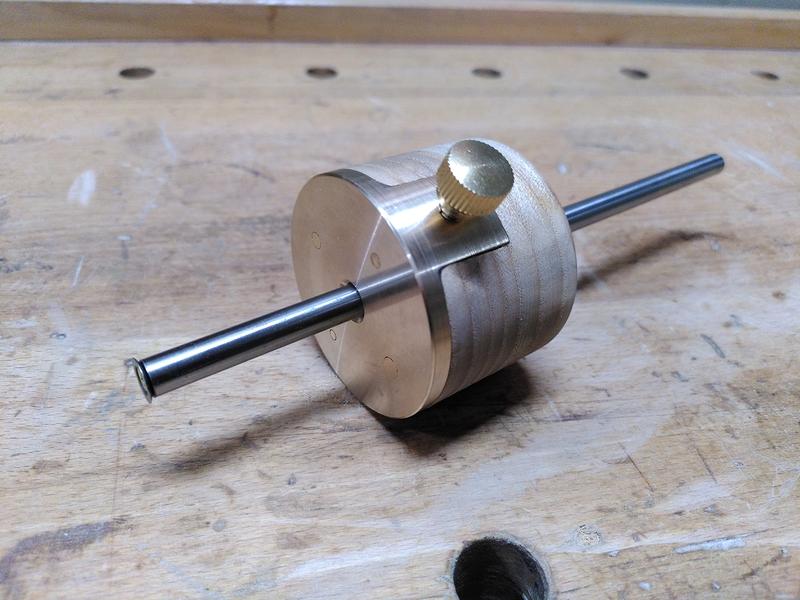
I had originally planned to make my own cutter, but in the end decided to use one from a veritas marking gauge. It make it easier to get replacements down the line. It’s designed to be held in place by an imperial screw. Hence the 82 ° counter sink in the end of the rod. Fortunately an M3 screw seems to hold it in place on the outside ok. The brass thumbscrew is an off the shelf item. I don’t yet have a knurler, and this seemed the easiest option.

The cutter recesses nicely into the face, leaving nothing proud. I’m a little annoyed that the screws didn’t disappear the way I had hoped they would But they don’t impair functionality.
It’s finished. and it works. It’s come out better than I ever hoped it could. It’s my most complicated machining project yet. And mixing the wood and brass like this adds a whole extra level of complexity.
I sent the finished photos to my friend.
“Beautiful. What is it?”
It’s a tool for identifying people who are handtool woodworkers, and those who aren’t.
Or it’s a marking guage. One or the other.