A Kerfed Project
Sun 04 January 2026 by JuliaNormally I use a drawing board for designing projects the old fashioned way with pencil and paper. But this project was the first where the design was sufficiently complex that I couldn't do the design on paper (without a lot of iterations), and so instead chose to design the basic mechanism using CAD. As I don't use CAD very often, and given most CAD packages don't so much have a learning curve, as a learning cliff. I opted for OpenSCAD for my design. It took me a few hours, studying photos I found for similar designs online, as well as testing iterations in CAD, before I had a design I thought might work.

With the design complete, I next needed to build it, and for that, I somehow needed to render the design from OpenSCAD into a form that is easy to work from in the workshop. OpenSCAD can do basic plots and things, but producing a drawing you can work from is not really its usecase. Fortunately FreeCAD has a technical drawing workbench, and can import OpenSCAD files. There followed an evening or three spent taking the OpenSCAD model and producing an engineering drawing of each part that I needed to make, the 5 individual parts spread nicely over two sheets of A4, I'd need to make two of each part for this project. There was nothing left to do now but order some stock, print the drawings, and head to the workshop.
This project requires three different metals for the various parts. Bronze, brass, and steel. I also used a piece of aluminium round bar as a sacrifial arbor to make machining the brass and bronze parts a lot easier, for a total metal count of four.
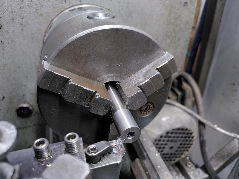
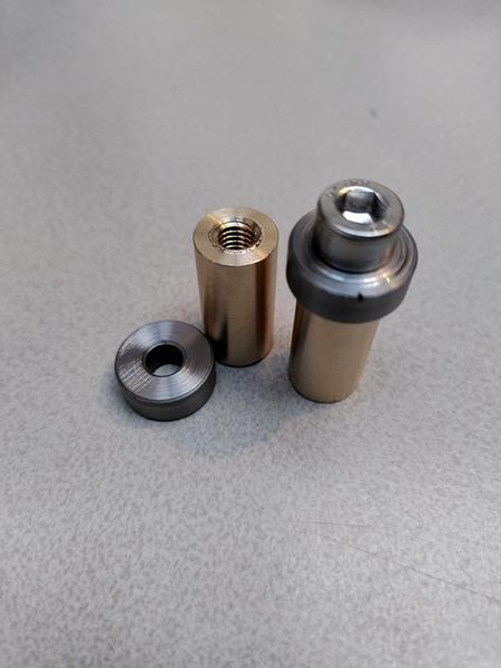
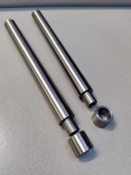
For the steel I chose to use precision ground 1.2510 (that's O1 for US/UK readers) round bar that was already 15mm in diameter. This is the nominal size for the first parts I wanted to make, the bearing caps. Fortunately, the 15mm isn't actually all that critical. Rather than spending time dialing in the stock in the four jaw chuck of the lathe, I decided to stick it in the three jaw, and take off just enough diameter to get it concentric. But first, I faced off the end, as is tradition. Then a cut of only a hundred microns or so was enough to bring it concentric. Centre drill the end, then drill out the middle. I chose to make both parts in one setup, parting off the first one, facing the end, then parting off the second. In hindsight what I should have done at this stage is spent some time polishing the face of the part before I parted it off. Something I will regret later, for many hours.
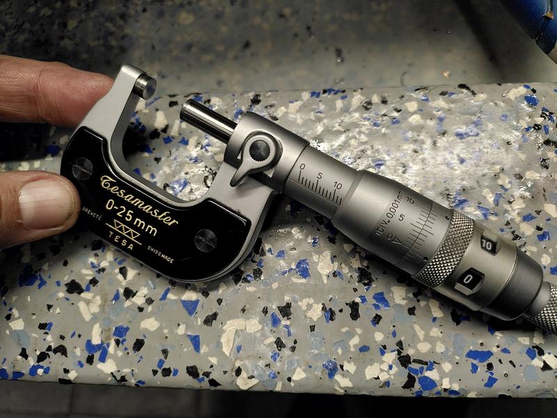
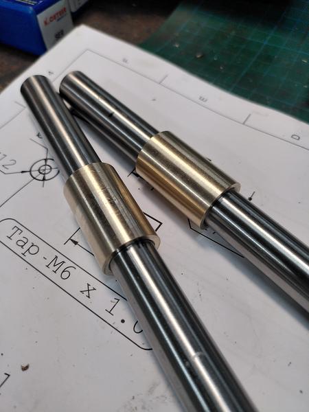
Order of operations on this project was something that I spent a lot of time thinking about. I could optimise for working on all the same material, then moving to the next, or based on the tools used. In the end the faff of swapping lathe chucks was the decider. I went with batching operations based on work holding. Next up was the pair of arm locks. These are made from brass stock. On the lathe they need to be taken to dimension, and then threaded M6 through the middle. Very little of the dimensions in this project are trully critical. Plus or minus 0.1mm or even larger wouldn't be the end of the world. So of course because tolerance wasn't an issue. I hit 12mm to within 4 microns...
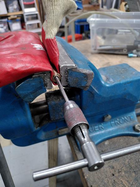
Due to the length of the tap I used, I couldn't quite go all the way through the part on the lathe, so after parting off, I chased the thread with the tap by hand in the vice, with some... um... improvised soft jaws. This also tidied up the threads where the parting tool had done its thing.
I now had four parts (remember all the metal parts for the final project are duplicated), and I could test things start to fit together. At this stage, just using an M6 bolt grabbed from the makerspace stock (and returned after testing).
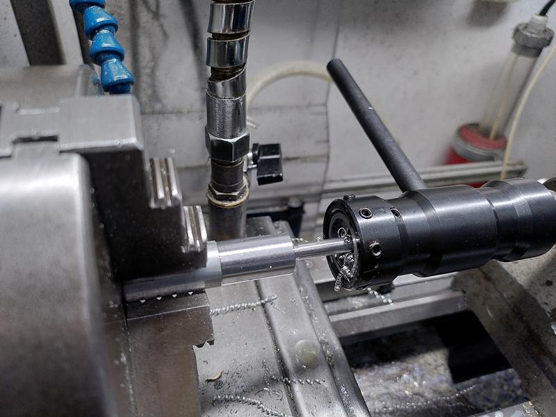
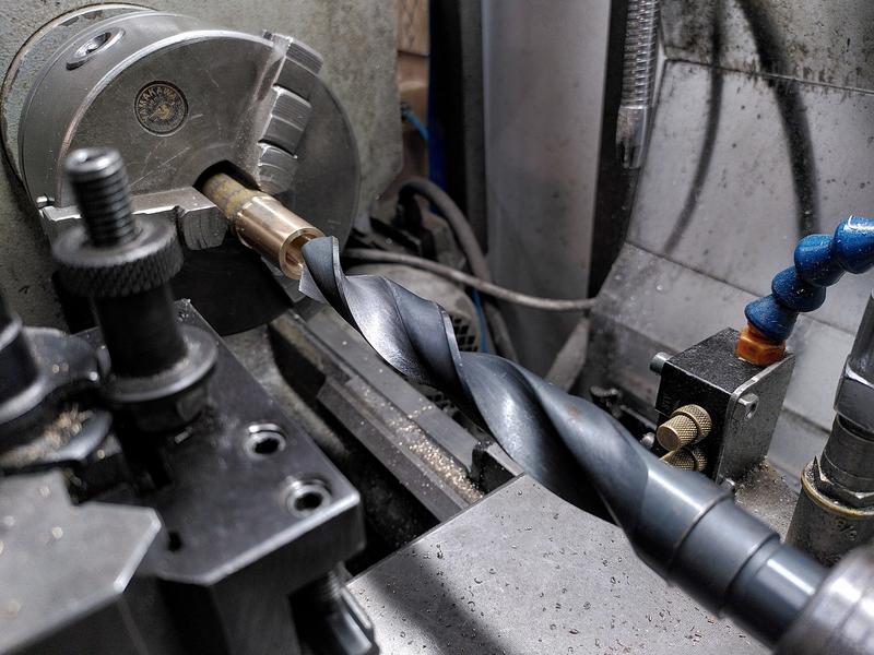
Next up was machining the sacrificial aluminium arbor I would need for work holding on the mill later. This is again a really simple part, with a 15mm diameter on one section, then an M6 threaded section. This was an opportunity to break out the tailstock die holder. A tool that makes cutting threads with a die on the lathe a lot easier.
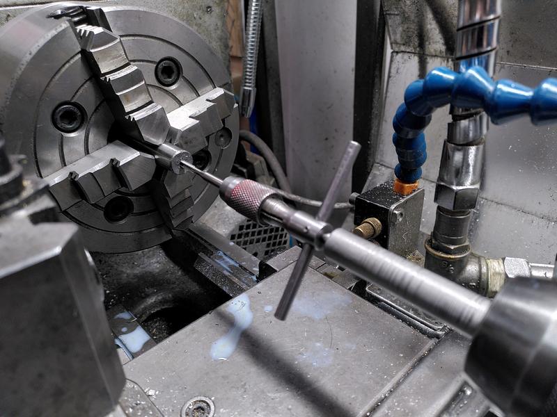
That concluded the work with the three jaw chuck for now, so it was time to swap in the four jaw, and begin the slow and laborious process of dialing in stock. Watching experienced machinists doing this makes it seem so easy. Yet for me it takes what feels like forever. Stock dialed in to within 10 microns, I faced off the end (as is tradition). Centre drilled, drilled, and then tapped a hole in the end with an 8-32 thread. Why the sudden weird thread in an otherwise metric project? One of the few purchased parts in this project are the saw bolts, they came with the blade I bought, which, being made in the US, are all using weird sizes. I could have chosen to make new metric ones, but as I already had these, it seemed silly to not use them.
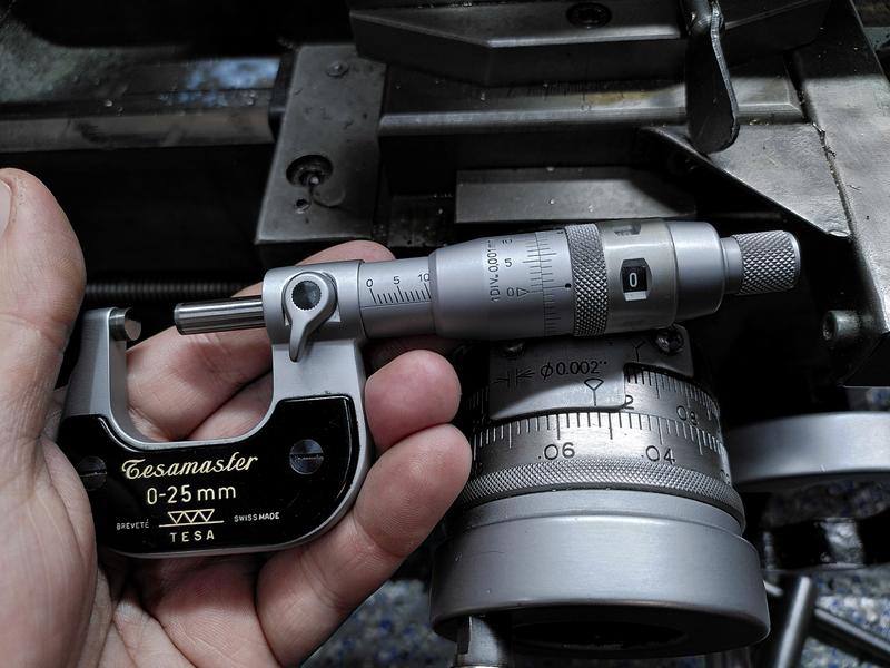
Next up was to machine a shoulder onto the end of the part. The dimension on the plans says 10mm, and is not especially critical. As I'll be machining the other part this interacts with, it can really be anything around 10mm. So of course I hit 9.996mm.
With the shoulder section machined on the long arm, I then made the cup that would interact with the end of the arm. This required boring out to 10mm a small recess. For this I had to buy a smaller boring bar as none of those I owned was small enough. The next operation on the steel arms, was to flip them in the four jaw, dial them in again, and bore the end out to about 10mm. This is largely for weight reduction and doesn't need great precision, so I used a normal 10mm twist drill for this. Dropping some chamfers around the end. The steel parts are now complete.
It was finaly time to work on the bronze parts. This meant swapping the three jaw chuck back into place, but I couldn't do it sooner as I was waiting on a 15mm reamer to arrive. But before I could ream the hole, first came the boring part (you honestly expect a machinist not to make this "joke"?). With the outer diameter taken to size, which I adjusted from the plan to 20mm after I realised I don't have a 19mm fortsner bit, but do have a 20mm one. This will become relevant when the project moves on to carbohydrate shaping later.
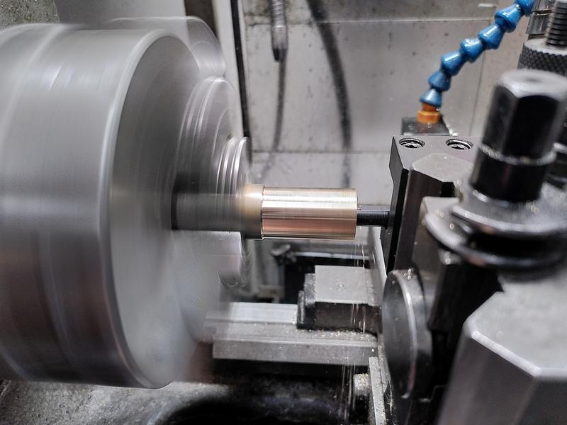
Once bored, I reamed the hole using my new 15mm reamer. This just left the problem of chamfering the hole. For which I took the opportunity to use the largest drill we have in the lathe tools selection, a 22mm drill with an MT2 shank.
The part was parted off, reversed in the chuck, and the same chamfer applied.
This concluded the lathe work (in theory) for the project.
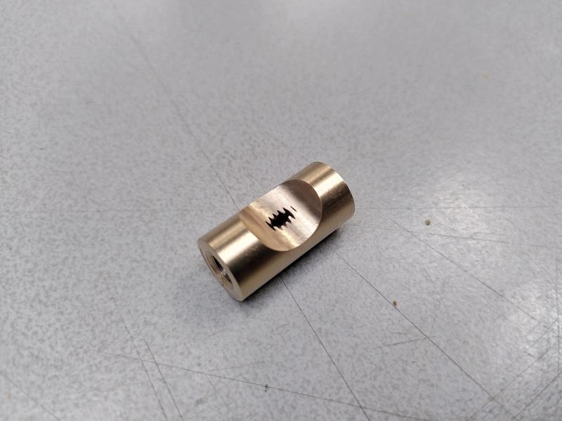
On the mill, I fitted the aluminium arbor I made earlier into a square collet block, held by the 15mm section I turned on the lathe, with just the M6 threaded part sticking out. The first arm lock was installed, held in place with a nyloc nut. A the centre finder was then used to find the middle of the part, then I could step over, and using a 15mm end mill, perform a plunge cut to take out a small section of the part.
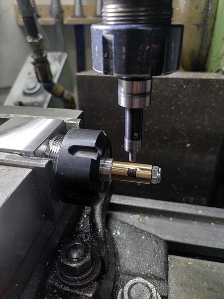
Except... I'm still very much a novice when it comes to using the centre finder, especially with the half function on the DRO. The first time I did the plunge cut it became evident I was very wrong in my position. This taught me an important lesson. And scrapped the part. Fortunately it was relatively simple to move back to the lathe, and remake the brass part so I could have another go on the mill, with the edge finder used correctly...
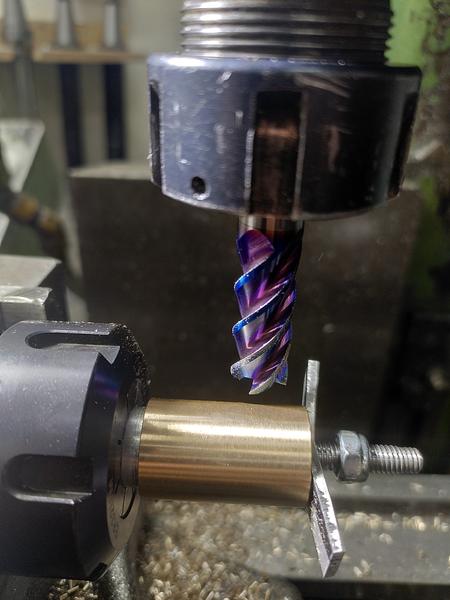
With the arm locks complete, the arbor was moved out so that the 15mm section was sticking out. The arm sleeve was installed, and held in place by a scrap of aluminium and the nyloc nut. The setup repeats on Y from the previous setup, requiring only edge finding on the end of the part for X. A 12mm end mill was used to make a plunge cut on the bronze part, taking a chunk out of the sacrifial aluminium too. With one part complete. The setup now repeats on X too.
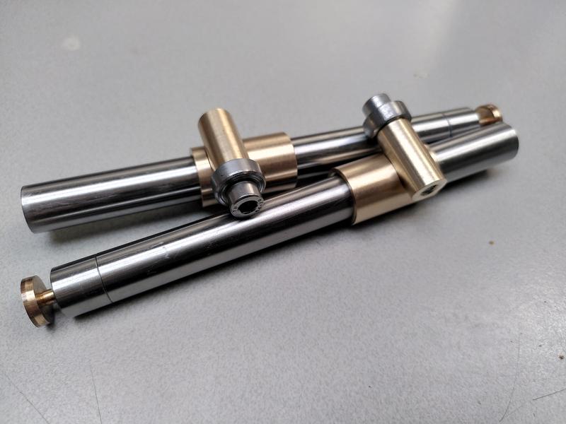
With that, all the metal working was done. I had two arms, two arm sleeves, two arm locks, two arm cups, and two bearing caps. Slotting them together to see that all the parts interacted the way I had hoped they would was a great relief.
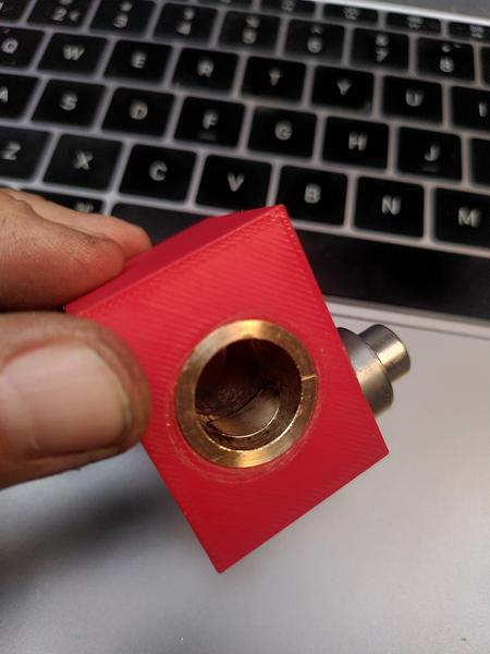
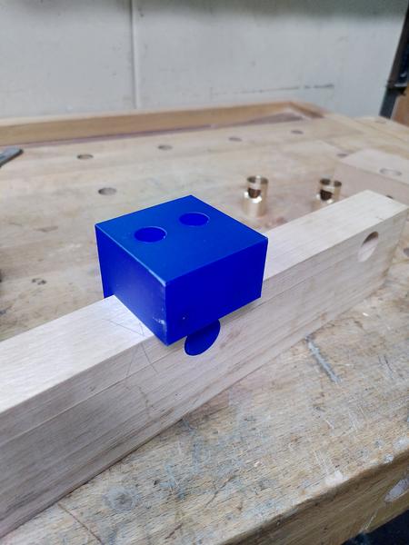
While the parts fitted together losely on the table just fine. I had no way of knowing if the mechanism of this design would work. Had I just spent 4 afternoons in the workshop machining up parts that don't work? Until I made the wooden body they would be installed in I wouldn't be sure. I needed an easy way to test. 3D printer to the rescue. Because I already had a CAD model of the design, it wasn't too difficult to make up a small test block that would hold the mechanism in the right place and allow me to test it. I could just create a cube, and subtract the design of the other parts. It didn't take long for the 3d printer to print, and I now had a block of PLA I could install my parts in and test.
The moment I slide the steel bar into place and cinched the screw down gently, it Works! Months of planning and thinking through how it works. Hours spent on CAD, multiple afternoons in the workshop. And it bloody well works!!
Not only did it work, but it worked better than I could ever hope for. The difference between locking the arm in place, and the arm sliding freely is a quarter of a turn. One quarter. 90˚. That's it. The tolerences are so close, that a single quarter turn is all it takes to lock the steel arm solid. It is really hard to explain the exquisite high felt when a design comes together like this. It was a good day.
Metalwork complete, mechanism proven to work. It was time to move to the woodworking area of the workshop. The body for the project is made from a piece of beech (fagus sylvatica) I had in stock. It was already planed to the right thickness. I just needed to slice it to size on the table saw. I would need a total of three pieces. Two for the fence, and one for the main body. I started with the fence. This would require two pairs of holes drilled precisely such that they intersect in the right place. For this, I opted for the simple option and made a 3d printed drilling guide to get the holes the exact spacing I need. Afterall, the woodworking pillar drill doesn't have a DRO to make positioning easier.
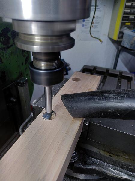
For the mechanism to function properly it is critical that the two holes that the sleeves are mounted in are absolutely parallel to each other, and perfectly perpendicular to the face of the fence. It is also critical that the hole for the arm lock is drilled in the exact correct position 90˚ to the orientation of the sleeves. To get this position correct, I made another 3d printed jig. This one had a 20mm long cylinder that went into the hole the sleeve would go in, and then had two 12mm holes on the top to act as drill guides. It was as I was making the second of these holes on the pillar drill that one of the other members of the makerspace came into the wood working area and broke one of the most important rules of using machine tools. DO NOT DISTRACT THE OPERATOR. He came up behind and said hello. I was in deep concentration, focusing on getting these holes in exactly the right position. When I jumped, I dropped the part, which broke the jig I had made, as well as damaging the wood. Words may have been had.
This did not put me in the best of moods. I completed the drilling as best I could. Went back to the work bench, and did a test install of the two sleeves and their arms.
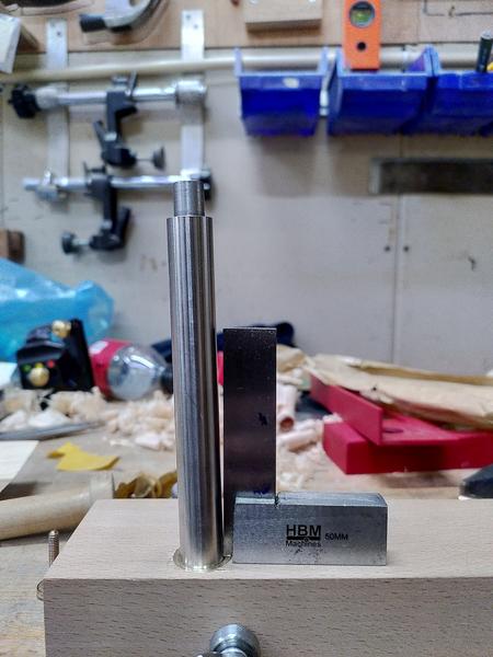
Now remember how I said these needed to exactly 90˚ to the face of the wood and parallel? After installing the metal parts and putting a square against the arm. I was absolutely horrified.
Between the breaking of the jig, my annoyance at the person who had startled me, and now the discovery that even the wooden part I had been working on was scrap. I gave up for the day. I packed up my toys, cleaned the machines I'd been using, and went home.
Laying in bed that night I tried to work out where the error had come from. The pillar drill runs up and down parallel to the pillar. It has to cut a hole that is parallel with it's axis, and the table is perpendicular to the pillar. Isn't it? I replayed the whole process over in my head. Step by step. Then it hit me. There's wobble in the bed of the pillar drill. That's where the error is coming from. That's why one of the holes did drill true. But when I moved the workpiece, the play in the position of the pillar drill table introduced the error. That had to be it. It wasn't me using the machines wrong. It wasn't my ability failure. I had just put false trust in a pillar drill being accurate. I just had to find a better tool for the job. I could use the pillar drill in the metal working area of the shop. But this needs to be really accurate, and when it comes to making really accurate holes, there's one tool that is the one to choose.
The Mill.
Now generally it's frowned upon to be cutting carbohydrates using the tools in the metal working area. Those are reserved only for working with boiled rocks. But. If you clean up after yourself, and don't leave sawdust all over the machines to attract moisture, and with it rust. Then you can do it.
I headed back to the workshop the next day with the remaining part of the beech wood. Before I started doing anything else tho, I started a new drill jig printing again on the 3d printer. It only takes about 45 minutes, and by the time I have done the first two holes, it'll be ready.
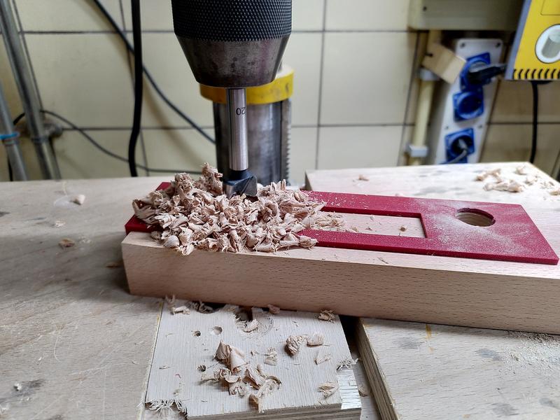
This time I didn't cut the wood to size in advance, giving me lots of room to screw up. I cleaned as much of the oil off the vice as I could, put in a set of parallels, and mounted the wood. I had marked out on the wood the rough position of the holes, this avoided the need to try and edge find on the wood. The critical dimension is the position of each hole relative to each other. I drilled the first hole based on the pencil marks I had made, then wound over on X using the DRO to find the right position, and drilled the second hole. All the time holding a vacuum cleaner hose next to the drill bit to catch as much of the chips as I could.
With both holes successfully drilled, I test fit the two bronze sleeves and the steel arms. They sat parallel. They sat 90˚ to the face. Phew. That was the first mistake from yesterday fixed. Now I just needed to drill the cross holes.
I took the drilling jig, still warm from the 3d printer, and slotted it into the wood.
I could have done these holes on the mill as well, either using the edge finder to get the position, or with the drill guide, but that's not an easy operation. Instead I chose to use the pillar drill from the metal working area of the workshop. This I knew does have the table setup perpendicular to the axis of the chuck, and it's a lot easier to get the position right with the drill jig. I drilled both cross holes in the wood, then took it back to the work bench. I could now install all the metal parts and check that it was right. They all fit perfectly. Tho it's a little bit of a faff getting the arms to line up perfectly with the scallop in the arm lock, while making sure the scallop in the sleeve lines up perfectly with the arm lock. But I got there in the end. I placed it on the bench. Sat down on the stool and looked at the project. I looked at the design. I looked at the workpiece. I looked back at the design.
Well f....
Adult Language In Progress
The cross hole for the front arm, was supposed to be drilled on the other side of the sleeve. That's why there are two holes in the drill guide. I got up and walked away. How could I scrap another part like this? argh. I grabbed a (non alcoholic) beer from the fridge, sat in the clean area of the makerspace and had a drink. Sitting there thinking about it. I realised that actually it doesn't matter. Only if you had access to the plans would you know that the hole was on the wrong side. Sure it's a suboptimal asthetic choice. But it doesn't actually affect the function of the tool. It'll still work just fine. Back to the workshop!
With the holes in the main body also drilled (15 on one side, 4mm through hole), I could test fit the whole thing together. It worked. It wasn't perfectly smooth yet, but it worked. That's good enough for this project.
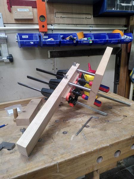
Drilling complete. I glued the smaller offset part to the fence. A task I made harder for myself, by not disassembling anything before hand. The main fence body was also still over length.
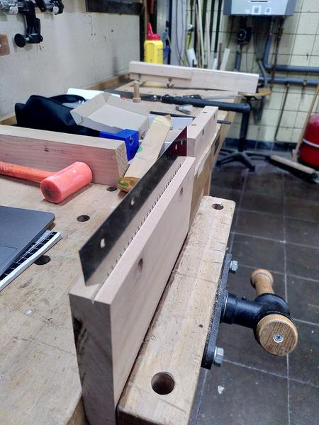
With the fence complete I now needed to cut a slot in the main body for the blade. For this the ideal tool to make that cut is of course. The blade itself. Except the blade doesn't yet have any form of handle. I mounted the body in the vice, and carefully cut the slot into it with the blade held in my hand. Not the stupidest thing I've done on this project, but possibly the most uncomfortable...
I could now reassemble the whole tool, and see how it all works together. There's still a lot of work to do, but it was starting to look like I had hoped, and most importantly the mechanism worked properly.
After cutting myself on the blade for what felt like the 10th time. I decided that perhaps a blade guard would be a good idea. I designed a simple blade guard in OpenSCAD, and printed it, using a pause in the 3d print as a chance to insert some magnets into voids in the main body of the print. Hitting resume, the printer encased the magnets holding them in place. No glue needed. It's not the strongest design, the magnets hold it in place on the blade, but could certainly do with a bit more holding strength. But that's a future improvement...
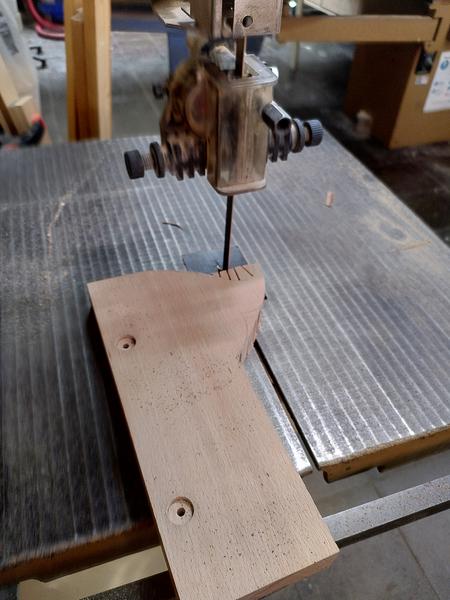
The main body of the tool was at this point still just a large flat rectangle, with all the lack of ergonomics that entails. I needed to do something to shape it. I chose to grab a template from blackburn tools (who I bought the blade from), to use as a rough outline for the main body. I traced round it, then took it to the bandsaw to make the cut. I didn't change the blade from the one that was in there, which was not an ideal blade for the curves, so it left me with some clearing up to do with a rasp, files, and sandpaper. But it removed the bulk of the material.
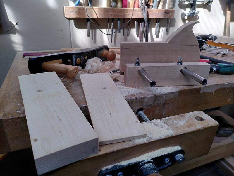
The tool was now essentially complete except for final fit and finish. But most importantly, it was complete enough that I could test it out. I grabbed a piece of 2x4 (well 44mm x 96mm) from the scrap wood bucket. Mounted it in the vice, and with the fence set to about 10mm. I made a cut along one edge the wood. It worked. The tooth geometry of the blade work great. One side done, I repeated it for the other three. I now had a kerf cut on all four sides. I grabbed my ryoba saw, inserted it into the kerf, and began to saw. The ryoba tracked in the kerf perfectly. Half way down I swapped the wood end for end in the vice and restarted the sawing from the other end. A minute or two later. The thin plank of pine parted from the rest of the 2x4.
IT WORKS.
The tool works. The design of my mechanism works. It does what I built it to do. Make thin boards without having to worry that my saw will wander. I sat back on the stool and admired my work. It wasn't finished yet. But the first 80% was done. The hardest 80% was complete. Now all I had to do to really finish it was the second 80%...
It this stage, work moved from the makerspace to home. Everything else that was left to do could be done with hand tools.
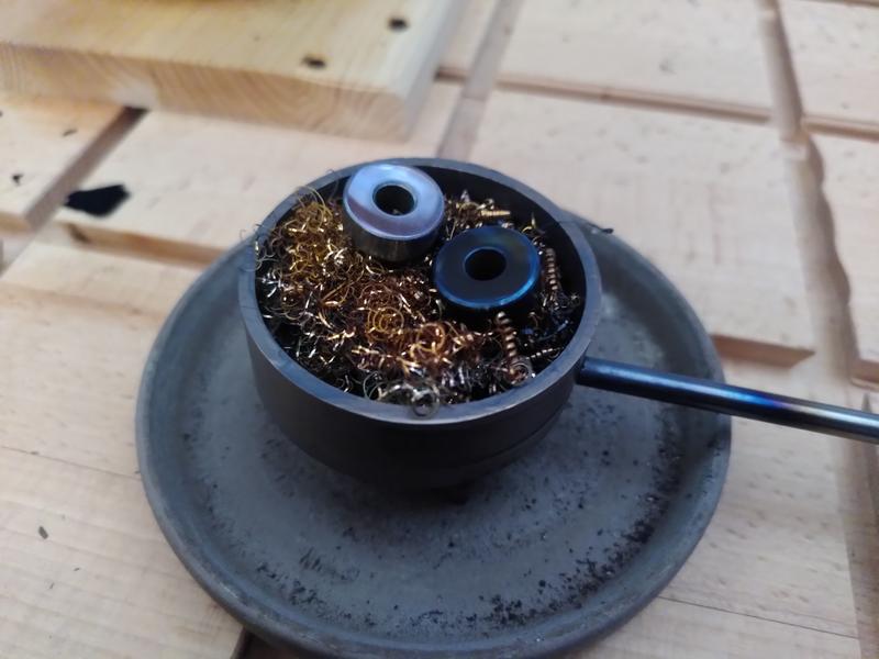
For some reason I decided that the best way to finish the steel bearing cap would be to hot blue them, perhaps I've been watching too many clickspring videos. But seeing as I have a blueing tray based on the clickspring design, Why not...
In hindsight, why not is the many hours of polishing it would take before I could blue the parts. I spent many many hours sat on the sofa, with a board on my lap, a piece of wet & dry paper on top, polishing these two 15mm diameter bearing caps. I thought I had got them done, I went from p240, all the way up to p3000. Then with a bright light shining, I spotted a scratch. Oh well, Back to the beginning, and up through the grits we go. I lost counts of how many times I did this. I just couldn't get the scratches out. I even went so far as to ask Chris from Clickspring himself for advice. But I was doing everything right. Chris suggested maybe I had some grit contamination on the sand paper. By this stage I'd already spent several evenings on polishing just these two parts alone. Dejected. I reinstalled them on the plane. Put the plane on the table. And walked away from the project.
Summer happened. Autumn came. The plane sat there on the work bench, that for reasons had moved from the balcony to my living room. Eventually, after staring at it for months, in December I decided that I couldn't let perfect be the enemy of good. I grabbed a fresh pack of wet & dry, stuck on a box set, and got to work. I took care going up through the grits. Doing each grit 90˚ to the previous. Trying as far as possible to get all the scratches out. Once I had got to P3000, I then moved to my leather sharpening strop with a green stropping compound. They weren't perfect. But I now had two very very shiny steel parts. All I needed to do now was blue them.
Initially I tried doing this using the heat from a small oil lap I had on the work bench. But it wasn't hot enough. So I grabbed the MAPP gas blow torch and used that. Watching as the part first went yellow, then got darker and darker before going blue. I fished the part out of the bluing tray with a pair of tweezers, and put it down on a piece of wood. Which started to smoke. Oh right, its really hot. I found a copper heat sink in the pile and put the part on that. Much better. No smoke. The second part went the same as the first. Just without the smoke.
Before, and after:
All that was left now was to finish off the wood body, apply a makers mark, and some finish. I set the plane up on the work bench, then with rasps, files, and finally sand paper, I removed the saw burn marks from where the band saw blade had been the wrong choice. I removed some of the pencil marks that were left over from construction. I smoothed out the other saw marks, and generally tidied up the outside of the plane body. I did a once over with 80 grit sand paper. Then with 180. Then I started again with 80 grit cos I realised I'd missed a bit. Eventually I had it in a state I was happy with. It was getting late in the evening and I had to stop for the night.
I resumed a few days later. There were just two remaining tasks on the todo list. Stamp my makers mark, and apply an oil finish. For the makers mark I wanted to use my new stamp, rather than the brand I've previously used. Yes this is blatantly inspired by Stavros Gakos' amazing planes. But hey, I have the stamp, of course I'm gonna try to use it.
I had to wait for an afternoon when a neighbour was using a hammer drill, so noone would be able to complain about the noise. Four thwacks with a hammer on my stamp, and my mark was left, both on the body of the plane, and also on the fence. It doesn't quite have the depth as when Stavros does it. But it's good enough. Two coats of danish oil later. And finally, eight months twenty eight days after I made the first chips. The project is complete.
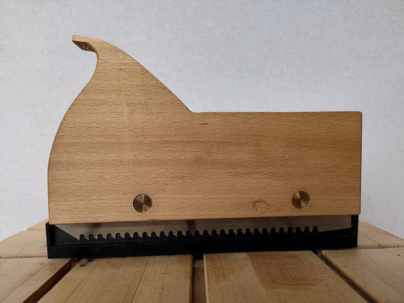
If you've managed to read all the way this far, first of all, thank you, it's really appreciated, however you're probably looking at this and thinking? That looks very nice. But what is it?
This is a tool called a Kerfing plane. Sometimes also called a Kerfing saw. It's used, as demonstrated above, to cut a kerf in a repeatable location all the way around a work piece prior to cutting off a thin plank. Like many, I first came across this type of tool after seeing Tom Figeon use one in his series The Good Doctors Medicine Cabinet. The one he uses was based on a kit made by Blackburn Tools. In 2020 I emailed Blackburn tools to ask to be put on the waiting list for the kit. In the mean time I ordered a kerfing saw blade and screws. That sat on the shelf while I waited for the kit to become available. Eventually in 2025, I finally managed to work out a design for the arm mechanism for the plane, and with no indication the kit would become available any time soon, I set about designing and making one. The design for the mechanism I came up with is definitely inspired by the Blackburn Tools mechanism. Tho obviously all the sizes (except one screw thread) are metric. I would have liked to have supported a small independent maker and bought the kit, were it available. But having now made a kerfing plane, I can fully understand why it's so hard to make this kit in a quantity sufficient to meet the demand. Especially as a one person operation. Obviously making the first one is the hardest, but it really makes me appreciate the effort involved in developing a product like this.
This project has had some of the most exquisite highs, as well as some of the biggest challenges I've ever had in a project. At times I've literally had to just pack up my tools and walk away, to rest and come back another day with a clear head, and a new approach. But now, sitting here looking at this tool I've built. It's the best project I've made to date.
Oh, and before anyone asks, I had originally planned to cut a hand hole like the blackburn tools template has. But I wanted to try it before I did, and without the hole I found it works really well. I can always add the hole later if I decide it needs it.
And now. The final result:
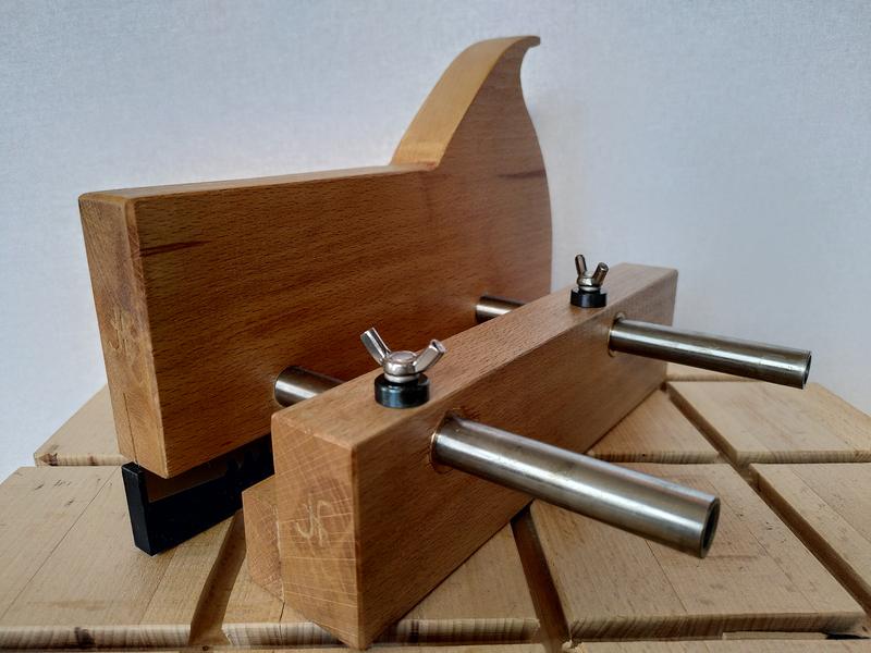
Front view:
Close up of the bluing:
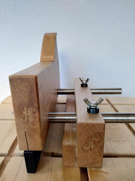
Side view: